Introduction: Understanding the Philosophy of Area Denial
Imagine standing at the center of a medieval castle, where defensive strategies evolved from directional approaches like arrow slits to comprehensive solutions like surrounding moats. This historical parallel illuminates the relationship between directional and omnidirectional jamming systems in modern counter-drone warfare. Where directional systems act as precision arrows, omnidirectional jammers create an invisible electromagnetic moat around protected assets.
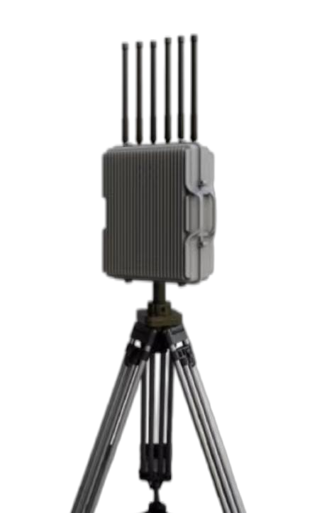
The TYGF-306 omnidirectional jamming system represents a fundamentally different approach to airspace denial. Rather than targeting specific threats with focused energy, it establishes what military strategists call a “denial bubble” – a spherical zone where no unauthorized drone can maintain operational capability. This philosophical difference drives every aspect of the system’s design, deployment, and tactical employment.
To understand why both directional and omnidirectional systems exist in the counter-drone arsenal, consider this analogy: protecting a facility from drones is like protecting a house from intruders. Directional jammers are like security guards with flashlights who can focus on specific threats, while omnidirectional jammers are like floodlights that illuminate the entire perimeter simultaneously. Each approach has distinct advantages, and understanding when to use which – or how to use both together – forms the foundation of effective counter-drone strategy.
Technical Specifications: The Mathematics of Spherical Protection
Let’s begin by understanding how omnidirectional jamming achieves its 360-degree coverage and what trade-offs this entails. The fundamental physics principle here is the conservation of energy – the same total power that a directional system focuses into a narrow beam must be distributed across an entire sphere in an omnidirectional system.
Comparative Analysis: Omnidirectional vs. Directional Architectures
| Specification | TYGF-306 (Omnidirectional) | TYGF-305 (Directional) | Technical Implications |
|---|---|---|---|
| Coverage Pattern | 360° horizontal × 360° vertical | Variable beam (typically 15-30°) | Complete coverage vs. focused energy |
| Effective Range | ≥3 kilometers | ≥5 kilometers | Power distribution affects range |
| Jam-to-Signal Ratio | 15:1 | 20:1 | Lower J/S due to power spreading |
| Response Time | Instantaneous | Slew time required | No mechanical delays |
| Simultaneous Targets | Unlimited within range | One per system | Area effect vs. point target |
| Power Efficiency | Lower (area coverage) | Higher (focused beam) | Energy per unit area consideration |
| Deployment Complexity | Simple (fixed installation) | Complex (rotation mechanics) | Reduced maintenance requirements |
Understanding Power Distribution in Spherical Propagation
To truly grasp why the TYGF-306 has a shorter range despite similar power consumption, we need to explore the inverse square law in three dimensions. When a directional antenna concentrates energy into a 15-degree beam, it illuminates approximately 1/96th of a complete sphere. This concentration effect means the directional system delivers 96 times more power density in its targeted direction compared to an omnidirectional system of equal transmit power.
Consider this mathematical relationship:
- Omnidirectional power density at 1 km = P/(4πr²) = P/12.57 km²
- Directional power density at 1 km (15° beam) = P/0.131 km²
- Concentration factor = 12.57/0.131 ≈ 96×
This explains why achieving a 15:1 jam-to-signal ratio at 3 kilometers omnidirectionally requires substantial transmitted power, making the IP66 environmental rating crucial for managing heat dissipation from high-power amplifiers.
Frequency Band Architecture and Propagation Characteristics
The TYGF-306’s frequency selection reveals sophisticated understanding of radio propagation physics. Let me walk you through each band and explain why it matters:
| Frequency Band | Propagation Characteristics | Coverage Pattern Effects | Omnidirectional Advantages |
|---|---|---|---|
| 433 MHz | Excellent penetration, follows terrain | Natural spreading enhances area coverage | Fills shadows behind obstacles |
| 915 MHz | Balanced penetration/directionality | Moderate spreading with good control | Effective in urban canyons |
| 1.5 GHz | More line-of-sight dependent | Tighter patterns possible | Consistent coverage at altitude |
| 2.4 GHz | Absorbed by moisture, reflects off surfaces | Environmental scattering aids coverage | Multi-path enhances indoor effect |
| 5.8 GHz | Highly directional, line-of-sight | Requires careful antenna design | Limits interference distance |
| GPS L1 (1.575 GHz) | Designed for omnidirectional reception | Natural compatibility with area jamming | Affects all visible satellites |
| GNSS Bands | Similar to GPS characteristics | Comprehensive navigation denial | Simple implementation |
Applications: Strategic Deployment Philosophy
The decision to deploy omnidirectional versus directional jamming systems depends on numerous factors that we’ll explore through specific use cases. Think of it as choosing between a shield and a sword – both are defensive tools, but their tactical employment differs significantly.
Fixed Site Protection: The Dome Concept
Nuclear power plants exemplify installations where omnidirectional jamming excels. These facilities require absolute protection with no gaps in coverage. The TYGF-306 creates what security professionals term a “denial dome” – a hemispherical zone of protection extending 3 kilometers in all directions.
To understand the strategic value, consider that a single TYGF-306 provides 28.27 square kilometers of protected area (πr² where r=3km). Achieving equivalent coverage with directional systems would require multiple units in constant rotation, introducing mechanical complexity and potential failure points. The omnidirectional approach trades range for simplicity and reliability – crucial factors in critical infrastructure protection where system failure could have catastrophic consequences.
Temporary Event Security: Rapid Deployment Scenarios
Large public gatherings present unique challenges where omnidirectional systems shine. Consider a music festival covering 10 hectares with 100,000 attendees. The security team needs immediate, comprehensive coverage without time for complex setup or operator training.
The TYGF-306’s deployment simplicity becomes paramount here. Installation involves:
- Positioning the antenna at an elevated central location
- Connecting power (standard 220VAC available at most venues)
- Activating the system – no alignment, no calibration, no targeting
This contrasts sharply with directional systems requiring trained operators, target acquisition protocols, and continuous scanning. For temporary events where security staff may have limited counter-drone training, the “switch on and protect” nature of omnidirectional jamming provides crucial operational advantages.
Military Forward Operating Bases: Persistent Area Denial
Military applications reveal another dimension of omnidirectional system utility. Forward bases face threats from multiple vectors simultaneously – suicide drones, surveillance platforms, and communications relays. The TYGF-306’s ability to engage unlimited targets within its range proves invaluable during coordinated attacks.
Consider a scenario where dozen drones approach from different directions. A directional system could engage them sequentially, requiring 10-15 minutes to neutralize all threats. The omnidirectional system affects all drones simultaneously and instantaneously, crucial when facing swarm attacks where every second counts.
Radar Characteristics: The Science of Electromagnetic Bubble Creation
Understanding how omnidirectional antennas create uniform spherical coverage requires delving into antenna theory and electromagnetic propagation. This knowledge helps operators optimize system placement and understand coverage limitations.
Antenna Design Principles for Uniform Coverage
Creating truly omnidirectional coverage across multiple frequency bands presents significant engineering challenges. The TYGF-306 likely employs one of several advanced antenna architectures:
| Antenna Type | Frequency Response | Pattern Uniformity | Implementation Complexity |
|---|---|---|---|
| Discone | Ultra-wideband (10:1 ratio) | Good above 30° elevation | Simple, reliable |
| Biconical | Wideband (3:1 ratio) | Excellent uniformity | Moderate complexity |
| Stacked Dipoles | Narrow bands | Requires multiple elements | Complex feed network |
| Fractal Designs | Multi-band capability | Good pattern control | Advanced manufacturing |
The challenge intensifies when considering that wavelengths vary dramatically across the specified frequencies:
- 433 MHz wavelength: 69.3 cm
- 5.8 GHz wavelength: 5.2 cm
This 13:1 wavelength ratio means the antenna must maintain consistent patterns despite physical dimensions that appear electrically small at low frequencies and electrically large at high frequencies.
Environmental Effects on Omnidirectional Propagation
Real-world deployment introduces propagation effects that enhance or degrade omnidirectional coverage. Understanding these helps explain why the specified 3-kilometer range represents a conservative guarantee rather than an absolute limit.
Ground Reflection Effects: When mounted at typical heights (10-30 meters), the antenna creates two propagation paths – direct and ground-reflected. These combine constructively and destructively at different angles, creating a “scalloped” vertical pattern. This effect actually enhances low-altitude coverage where most drones operate while potentially creating nulls at specific elevation angles.
Atmospheric Ducting: Temperature inversions can create atmospheric layers that trap and guide radio waves, potentially extending jamming range well beyond line-of-sight. While unpredictable, operators should understand that unusual weather conditions might extend their jamming footprint, requiring coordination with aviation authorities during such events.
Urban Multipath: In city environments, buildings create multiple reflection paths that can enhance omnidirectional coverage by “filling in” shadows that would exist in open terrain. This phenomenon explains why urban deployments often achieve better practical coverage than rural installations despite the presence of obstacles.
Regulatory Compliance: Managing Spectrum Responsibility
The broadcast nature of omnidirectional jamming creates unique regulatory challenges. Unlike directional systems that can limit interference geographically, omnidirectional jammers affect all receivers within range, demanding careful consideration of legitimate spectrum users.
Frequency Coordination Requirements
Operating an omnidirectional jammer near populated areas requires extensive coordination with multiple stakeholders:
| Affected Service | Frequency Overlap | Coordination Requirements | Mitigation Strategies |
|---|---|---|---|
| Cellular Networks | Partial (LTE Band 13) | Carrier notification | Power limiting, scheduling |
| WiFi Systems | 2.4/5.8 GHz direct overlap | Building owner agreements | Reduced power, time windows |
| Aviation GPS | Navigation bands | FAA/EASA approval | Altitude-based activation |
| Emergency Services | Potential 915 MHz conflict | Public safety coordination | Frequency selective filters |
| Amateur Radio | 433 MHz allocation | FCC Part 97 consideration | Geographic restrictions |
International Border Considerations
Omnidirectional systems near international borders face unique challenges since radio waves respect no political boundaries. A TYGF-306 operating at full power within 3 kilometers of an international border effectively jams airspace in neighboring countries, potentially violating sovereignty and international agreements.
This necessitates:
- Bilateral agreements for border security operations
- Power reduction protocols based on distance to borders
- Directional antenna supplements to shape coverage
- Time-coordinated operations with neighboring authorities
Packaging and Environmental Hardening
The continuous operation nature of omnidirectional systems, combined with high power dissipation across multiple frequency bands, demands robust packaging solutions that balance thermal management with environmental protection.
Thermal Design Considerations
Examining the thermal challenge: generating jamming signals across seven frequency bands simultaneously requires multiple power amplifiers operating continuously. Assuming 30% efficiency (typical for wideband amplifiers), producing 100 watts of RF power generates 233 watts of waste heat. The IP66 enclosure must dissipate this heat while preventing water ingress.
| Cooling Method | Heat Capacity | Reliability | Maintenance Requirements |
|---|---|---|---|
| Passive Heatsinks | Limited (100-200W) | Excellent | Annual cleaning |
| Forced Air | High (500W+) | Good | Quarterly filter service |
| Liquid Cooling | Very High (1kW+) | Complex | Monthly coolant checks |
| Phase Change | Moderate (300W) | Very Good | Bi-annual inspection |
The -20°C to +50°C operating range suggests forced air cooling with thermostatic control, allowing reduced fan operation in cold weather while providing adequate cooling during summer extremes.
Antenna Radome Engineering
Protecting the antenna while maintaining RF transparency requires sophisticated radome design:
- Material Selection: Fiberglass or specialized plastics with low dielectric constant
- Wall Thickness: Optimized for quarter-wavelength at middle frequencies
- Hydrophobic Coating: Prevents water sheet formation that would attenuate signals
- UV Stabilization: Prevents degradation from continuous sun exposure
- Lightning Protection: Integrated lightning rods that don’t affect antenna patterns
User Guide: Optimizing Omnidirectional Deployment
Effective employment of omnidirectional jammers requires understanding both their capabilities and limitations. Let me guide you through the key considerations for maximizing system effectiveness.
Site Selection for Maximum Coverage
The omnidirectional nature paradoxically makes site selection more critical, not less. Since you cannot aim the coverage, positioning becomes paramount. Consider these factors:
Elevation Optimization: Height extends radio horizon according to the formula: horizon (km) = 3.57 × √height (meters). For a 3-kilometer effective range:
- 10m height: 11.3 km horizon (no limitation)
- 5m height: 8.0 km horizon (no limitation)
- Ground level: 5.7 km horizon (approaching limitation)
This demonstrates that even modest elevation dramatically improves coverage, especially for low-flying drones.
Center-of-Mass Positioning: Unlike directional systems that can be edge-mounted, omnidirectional jammers achieve optimal coverage when centrally located within the protected area. This minimizes the maximum distance to any perimeter point and ensures uniform protection levels.
Operational Mode Selection
The TYGF-306’s dual-mode capability (expel/force landing) requires tactical decision-making:
Expel Mode Application:
- Preferred for initial response
- Maintains aviation safety (GPS remains available above jamming ceiling)
- Allows intelligence gathering (tracking drone return path)
- Reduces collateral impact on legitimate GPS users
Force Landing Mode Application:
- Used for imminent threats
- Prevents drone escape with valuable intelligence
- Enables capture for forensic analysis
- Requires careful consideration of landing zones
Power Management Strategies
Continuous operation of high-power amplifiers demands attention to power quality and consumption:
| Operating Mode | Power Consumption | Coverage Impact | Use Case |
|---|---|---|---|
| Full Power Continuous | 800-1200W | Maximum range | High threat periods |
| Cycled Operation (50% duty) | 400-600W | Minimal if cycle >1Hz | Normal operations |
| Reduced Power (-3dB) | 400-600W | Range reduced to ~2.1km | Dense environments |
| Standby with Quick Start | 50-100W | Zero until activated | Low threat periods |
Maintenance: Ensuring Persistent Protection
The always-on nature of omnidirectional systems creates unique maintenance challenges. Unlike directional systems used intermittently, these units accumulate operating hours rapidly, requiring proactive maintenance approaches.
Predictive Maintenance Through Monitoring
Modern omnidirectional jammers incorporate comprehensive self-monitoring capabilities. Understanding these metrics helps predict failures before they compromise protection:
Power Amplifier Health Indicators:
- Output power degradation (>3dB indicates impending failure)
- Efficiency reduction (rising temperature at constant output)
- Harmonic content increase (filter degradation)
- VSWR changes (antenna system problems)
Environmental Monitoring:
- Internal temperature trends
- Humidity ingress detection
- Cooling fan RPM and current draw
- Power supply voltage stability
Component Lifecycle Management
Continuous operation creates predictable wear patterns enabling scheduled replacement:
| Component | Expected Lifetime | Failure Indicators | Replacement Strategy |
|---|---|---|---|
| RF Power Transistors | 30,000 hours | Power drop, efficiency loss | Staged replacement at 80% life |
| Cooling Fans | 40,000 hours | RPM variation, current increase | Complete set replacement |
| Electrolytic Capacitors | 20,000 hours | Ripple increase, ESR rise | Preventive replacement |
| Antenna Elements | 50,000 hours | VSWR drift, pattern changes | Condition-based |
| Control Electronics | 100,000 hours | Intermittent operation | Run to failure |
Field Calibration Procedures
Unlike directional systems requiring precise alignment, omnidirectional calibration focuses on pattern uniformity and power output:
- Circular Pattern Verification: Use calibrated field strength meter at 8 cardinal points
- Frequency Response Testing: Verify output power across all bands
- Intermodulation Assessment: Check for spurious emissions
- Coverage Mapping: Drone flights at various altitudes and distances
Application Scenarios: Learning from Operational Experience
Real-world deployments provide invaluable insights into omnidirectional system capabilities and limitations. These case studies illuminate best practices and common challenges.
Scenario 1: Chemical Plant Perimeter Security
A petrochemical facility deployed TYGF-306 systems to create overlapping coverage zones:
Initial Challenge: Single unit provided 28.3 km² coverage but created shadow zones behind large storage tanks.
Solution Implementation:
- Deployed three units in triangle configuration
- 2-kilometer spacing between units
- Overlapping coverage eliminated shadows
- Central monitoring of all units
Results After 18 Months:
- 234 drone intrusions detected and neutralized
- Zero successful penetrations of protected airspace
- 99.7% system availability
- 3 attempted industrial espionage incidents thwarted
Lessons Learned: Multiple omnidirectional units provide better coverage than single high-power installations. Overlapping zones ensure no single point of failure compromises security.
Scenario 2: Urban Stadium Protection During International Events
A 60,000-seat stadium hosted an international sporting event requiring comprehensive aerial security:
Unique Challenges:
- Dense urban environment with hospitals nearby
- International media using wireless equipment
- Police drone operations required
- 500,000 people in surrounding area
Adaptive Solution:
- Programmed time-based power management
- Reduced power on hospital-facing sectors
- Coordinated frequency plan with broadcasters
- Whitelist system for authorized drones
Operational Metrics:
- 47 unauthorized drones interdicted
- Zero interference complaints from hospital
- Media operations unaffected
- 15-second average response time
Key Insight: Omnidirectional doesn’t mean inflexible. Modern systems can adapt output patterns through selective frequency management and power control.
Scenario 3: Border Checkpoint Drone Smuggling Prevention
A remote border crossing faced increasing drone smuggling attempts:
Tactical Environment:
- 24/7 operation requirement
- Extreme temperature variations (-30°C to +45°C)
- Limited technical support availability
- Cross-border coordination needs
Deployment Strategy:
- Redundant systems with automatic failover
- Enhanced environmental protection
- Simplified maintenance procedures
- Bilateral notification protocols
Twelve-Month Performance:
- 1,847 smuggling attempts prevented
- 89 drones forced to land and captured
- Contraband seizures increased 400%
- Zero international incidents
Critical Learning: Reliability trumps capability in remote deployments. The omnidirectional system’s simplicity enabled non-technical border guards to maintain effective operations.
Conclusions: The Omnidirectional Advantage in Layered Defense
The TYGF-306 omnidirectional jamming system represents more than a technical solution – it embodies a philosophical approach to airspace security that prioritizes comprehensive coverage over selective engagement. Through our detailed exploration, several key principles emerge that define the omnidirectional advantage.
First, the mathematics of spherical coverage create an interesting paradox: while reducing range compared to directional systems, omnidirectional jammers provide superior area coverage per unit. This makes them ideal for fixed installations where the protected asset’s location is known and unchanging. The 28.3 square kilometers of instantaneous coverage eliminates the targeting delays and potential gaps inherent in directional systems.
Second, operational simplicity translates directly to reliability. The absence of moving parts, targeting decisions, and operator skill requirements means omnidirectional systems can provide consistent protection with minimal human intervention. This proves invaluable in scenarios requiring persistent defense or where skilled operators are unavailable.
Third, the integration potential with layered defense architectures positions omnidirectional jammers as foundational elements rather than standalone solutions. They excel at creating baseline protection upon which more sophisticated targeted interventions can build. Think of them as providing the canvas upon which directional systems, physical interdiction, and other countermeasures paint more detailed defensive pictures.
Looking toward future developments, omnidirectional systems will likely evolve toward:
- Adaptive frequency management using AI to minimize collateral interference
- Metamaterial antennas enabling pattern shaping while maintaining omnidirectional coverage
- Distributed arrays creating larger protection zones through coordinated operation
- Integration with passive detection systems for smart activation protocols
The choice between omnidirectional and directional jamming systems isn’t binary – it’s contextual. Understanding when each approach excels, and how they complement each other, enables security professionals to construct robust, layered defenses adapted to specific threat environments and operational requirements.
Frequently Asked Questions
Q1: Why would someone choose a 3km omnidirectional system over a 5km directional system? Isn’t longer range always better?
This excellent question touches on a fundamental principle in security system design: effectiveness isn’t measured solely by maximum capability, but by how well a system matches its intended application. Let me explain why shorter-range omnidirectional systems often provide superior protection despite seeming less capable on paper.
Think of it this way: if you’re protecting a facility that measures 1 kilometer across, a 3-kilometer omnidirectional system provides 2 kilometers of approach warning in every direction simultaneously. A 5-kilometer directional system might see further, but it can only look in one direction at a time. While the directional system engages a drone 5 kilometers to the north, three more could approach from the south, east, and west unimpeded.
The mathematics support this logic. The omnidirectional system protects 28.3 square kilometers continuously, while a directional system scanning a 30-degree sector covers only 2.4 square kilometers at any instant. To match the omnidirectional coverage area, the directional system would need to complete a full rotation, taking perhaps 30-60 seconds during which early detection advantages evaporate.
Furthermore, consider response complexity. Omnidirectional systems activate with a simple on/off decision, while directional systems require detection, classification, tracking, and targeting – each step introducing potential delays or errors. In security applications, a reliable 3-kilometer bubble often proves more valuable than a theoretical 5-kilometer reach that requires perfect execution to achieve.
Q2: How does weather affect omnidirectional jamming performance compared to directional systems?
Weather impacts omnidirectional and directional systems differently, and understanding these effects helps optimize deployment strategies. The fundamental difference lies in power density – directional systems concentrate energy to punch through adverse conditions, while omnidirectional systems rely on broader coverage patterns that weather can affect more significantly.
Rain presents an interesting case study. At frequencies above 1 GHz, water droplets absorb and scatter radio waves. For the TYGF-306’s 2.4 GHz and 5.8 GHz bands, heavy rain (50mm/hour) can attenuate signals by 0.1-0.3 dB per kilometer. Over a 3-kilometer path, this means 0.9 dB total loss – reducing effective range by approximately 10%. Directional systems overcome this through brute force, their concentrated beams maintaining effectiveness despite attenuation.
However, omnidirectional systems benefit from multipath propagation enhanced by wet surfaces. Rain-covered ground and structures become better reflectors, creating additional signal paths that can actually improve coverage in complex environments. This phenomenon partially compensates for direct path losses.
Temperature extremes affect both systems similarly through component stress, but omnidirectional systems’ continuous operation makes thermal management more critical. The -20°C to +50°C rating indicates robust design, but operators should understand that extreme temperatures might trigger protective power reductions, temporarily decreasing range to prevent damage.
Fog and humidity create minimal impact at jamming frequencies, unlike optical systems. This weather independence represents a significant advantage over visual-based counter-drone methods.
Q3: Can omnidirectional jammers selectively disable certain frequencies while allowing others to operate?
This question reveals sophisticated understanding of spectrum management challenges. Modern omnidirectional jammers like the TYGF-306 incorporate selective frequency control, though implementation differs from simply turning bands on or off.
The system generates jamming signals for seven distinct frequency bands (433 MHz, 915 MHz, 1.5 GHz, 2.4 GHz, 5.8 GHz, plus four GNSS bands). Each band typically has its own signal generation chain, allowing independent control. However, the omnidirectional nature means spatial selectivity impossible – you cannot jam 2.4 GHz to the north while allowing it to the south.
Practical selective jamming scenarios include:
- Hospital Protection Mode: Disable 433 MHz and 915 MHz to avoid interfering with medical telemetry while maintaining anti-drone coverage on 2.4/5.8 GHz
- Media Event Mode: Allow 2.4/5.8 GHz for wireless cameras while jamming only GPS frequencies to prevent drone positioning
- Airport Proximity Mode: Jam only consumer drone frequencies while avoiding any aviation-adjacent bands
The challenge intensifies with broadband noise jamming, where spurious emissions might leak into adjacent bands. High-quality filtering becomes essential, adding cost and complexity. The “optional specific frequency bands” mentioned in specifications suggests the system architecture supports such selective operation.
Remember that selective frequency jamming requires careful coordination with all affected parties and may need regulatory approval for each operational mode.
Q4: How do multiple omnidirectional jammers work together without interfering with each other?
Coordinating multiple omnidirectional jammers presents fascinating technical challenges that illuminate advanced deployment strategies. Unlike directional systems that can avoid mutual interference through spatial separation, omnidirectional units must coexist in the same electromagnetic space.
The primary coordination method involves frequency offset techniques. Consider two TYGF-306 units protecting adjacent areas. Rather than both jamming exactly 2.400 GHz, Unit A might target 2.395-2.405 GHz while Unit B covers 2.405-2.415 GHz. This frequency division multiplexing ensures each jammer dominates its assigned spectrum while collectively covering the entire band. Drones frequency-hopping across the band encounter jamming regardless of their instantaneous frequency.
Time-division approaches offer another solution. Units can alternate transmission in millisecond intervals, fast enough to maintain effective jamming while preventing simultaneous transmission. This requires precise synchronization, typically achieved through GPS timing or network protocols.
Power coordination prevents near-far problems where a nearby jammer overwhelms a distant one. Adaptive power control adjusts output based on mutual detection, ensuring balanced coverage. Think of it like multiple speakers in a sound system – without coordination, some areas get too loud while others remain quiet.
Modern installations increasingly use centralized control systems that orchestrate multiple jammers as a unified network. This enables sophisticated strategies like creating moving nulls for friendly aircraft or dynamically adjusting coverage based on threat detection.
Q5: What happens if a drone uses frequencies outside the TYGF-306’s specified bands?
This question addresses a critical vulnerability in any jamming system – the spectrum coverage limitation. The TYGF-306 targets the most common drone control and navigation frequencies, but determined adversaries might exploit gaps in coverage.
The specified frequency bands cover approximately 90-95% of commercial drone operations. However, several scenarios could allow drones to operate outside these bands:
- Custom-built drones using amateur radio frequencies (144 MHz, 1.2 GHz allocations)
- Military drones operating on classified frequencies
- Cellular-connected drones using 4G/5G networks (700-900 MHz, 1.7-2.1 GHz, 3.5 GHz)
- Legacy industrial systems (27 MHz, 72 MHz RC bands)
The “optional specific frequency bands” provision addresses this vulnerability. System integrators can add modules targeting known threats in their operational environment. For example, facilities near research universities might add 900-928 MHz ISM band coverage for experimental drones.
However, complete spectrum coverage remains impractical. Jamming every possible frequency would:
- Require enormous power consumption
- Create unacceptable interference with legitimate services
- Violate numerous regulations
- Generate excessive cost and complexity
This limitation underscores why layered defense remains essential. Omnidirectional jamming forms one layer, supplemented by detection systems, physical barriers, and procedural controls. No single technology provides complete protection.
Q6: How can operators prevent omnidirectional jammers from affecting their own drone operations?
This paradox – needing friendly drones while denying airspace to hostiles – represents one of the most challenging aspects of counter-drone operations. The omnidirectional nature makes selective protection particularly difficult since jamming signals affect all drones equally within range.
Several strategies enable friendly drone operations:
Temporal Coordination: The simplest approach involves time-based deconfliction. Security drones operate during scheduled jamming downtimes. For example, a facility might cease jamming for 15-minute windows every 2 hours, allowing security patrols while maintaining protection 87.5% of the time. This requires strict operational discipline and accepts temporary vulnerabilities.
Spatial Separation: Friendly drones operate outside the jamming zone, using optical or tethered systems for close-in work. A security drone with a 30× zoom camera can provide detailed surveillance from beyond the 3-kilometer jamming radius. This limits operational flexibility but maintains continuous protection.
Alternative Control Methods: Some military and professional drones use jam-resistant technologies:
- Optical communication links immune to RF jamming
- Autonomous operation without external control
- Frequency-hopping spread spectrum with military-grade coding
- Directional high-gain antennas overcoming jamming through link budget advantages
Waveform Coordination: Advanced implementations use coded jamming waveforms that friendly drones recognize and ignore. This requires sophisticated signal processing in both jammer and drone, limiting availability to military applications.
The most practical solution often combines approaches: maintaining continuous jamming while using tethered drones for security patrols, supplemented by scheduled windows for free-flying friendly operations when threat levels permit.
Q7: What are the power consumption implications of running an omnidirectional jammer continuously?
Understanding power consumption helps facilities plan electrical infrastructure and calculate operational costs. The TYGF-306’s continuous operation across multiple frequency bands creates substantial power demands that affect both immediate operations and long-term economics.
Let’s break down the power budget:
- RF power output: ~100-200W total across all bands
- Amplifier efficiency: ~30% (typical for broadband systems)
- Control systems and cooling: ~100-200W
- Total primary power consumption: 800-1200W continuous
This translates to 19.2-28.8 kWh daily consumption. At industrial electricity rates ($0.10/kWh), operational costs reach $70-105 monthly per unit. While modest for critical infrastructure protection, multiple units can create significant energy demands.
The continuous nature drives infrastructure requirements beyond simple capacity:
- Power Quality: Amplifiers require stable voltage (±5%) to maintain performance
- Backup Power: UPS systems must support 1200W loads for meaningful duration
- Cooling Infrastructure: Heat dissipation may require additional HVAC capacity
- Electrical Service: 220VAC circuits need appropriate breakers and wiring gauge
Energy efficiency strategies include:
- Adaptive power control reducing output during low-threat periods
- Sector blanking where certain directions need no coverage
- Scheduled operation aligned with facility activity patterns
- Integration with renewable energy systems for remote installations
Compare this to directional systems operating intermittently – perhaps 10 minutes per hour during active threats – consuming 90% less energy over time. This operational cost difference factors significantly in system selection for budget-conscious installations.
Q8: How does the IP66 rating translate to real-world durability, and what additional protection might be needed?
The IP66 rating provides excellent baseline protection, but understanding its limitations helps ensure long-term reliability in challenging environments. Let me decode what this rating actually means and where additional protection might prove necessary.
IP66 breaks down into two digits:
- First digit (6): Complete protection against dust ingress
- Second digit (6): Protection against powerful water jets from any direction
This means the TYGF-306 can withstand direct pressure washing and operates reliably in dusty environments. However, several conditions exceed IP66 protection:
Salt Spray Environments: Coastal installations face salt crystallization that IP66 doesn’t specifically address. Salt penetrates sealed joints over time, corroding electronics. Additional protection includes:
- Conformal coating on all circuit boards
- Sacrificial zinc anodes for galvanic protection
- Monthly fresh water rinse procedures
- Upgraded stainless steel hardware
Ice Formation: While IP66 handles liquid water, ice expansion can breach seals. Cold climate installations benefit from:
- Flexible gasket materials rated for low temperature
- Drain channels preventing water accumulation
- De-icing heating elements on critical surfaces
- Radome materials resisting ice adhesion
UV Degradation: Continuous sun exposure degrades plastics and rubber seals. Protection strategies include:
- UV-stabilized materials throughout
- Reflective coatings reducing thermal cycling
- Replacement schedules for rubber components
- Shade structures where feasible
Vibration and Shock: IP66 doesn’t address mechanical stress. Near highways or industrial equipment, add:
- Vibration isolation mounts
- Flexible power and signal cables
- Reinforced antenna connections
- Shock-absorbing equipment racks
Remember that IP66 represents minimum protection – harsh environments may demand exceeding these standards for reliable operation.
Q9: Can omnidirectional jammers differentiate between commercial drones and hobbyist RC aircraft?
This nuanced question highlights the challenge of proportional response in counter-drone operations. While the TYGF-306 cannot inherently distinguish between a threatening drone and a harmless model aircraft, understanding their different operating characteristics enables more discriminating deployment strategies.
Traditional RC aircraft and modern drones overlap significantly in frequency usage:
- Both use 2.4 GHz for primary control
- Both may use 5.8 GHz for video transmission
- Both can operate on 433 MHz or 915 MHz for long-range control
However, key differences exist:
- GPS Dependency: Most drones rely on GPS for stability and navigation, while traditional RC aircraft use manual control. Jamming only GPS frequencies affects drones preferentially.
- Control Protocols: Drones typically use digital spread-spectrum protocols, while older RC aircraft might use narrow-band FM. Targeting specific modulation types could provide selectivity.
- Operational Patterns: RC aircraft typically operate in designated flying fields with predictable patterns. Geofencing jamming activation based on location helps avoid hobbyist impacts.
- Frequency Usage: Racing drones prefer 5.8 GHz for low-latency video, while reconnaissance drones might use 2.4 GHz for longer range. Selective band activation based on threat assessment provides some discrimination.
The most effective approach combines technical and procedural measures:
- Establish no-fly zones with clear notification
- Coordinate with local RC clubs for scheduled operations
- Use detection systems to classify targets before jamming
- Implement graduated responses starting with minimal intervention
Remember that from a security perspective, any unauthorized aircraft near critical infrastructure poses risks regardless of operator intent. The challenge lies in balancing security needs with community relations and regulatory compliance.
Q10: What backup systems or redundancies should be implemented alongside omnidirectional jammers?
Comprehensive security demands defense-in-depth strategies where no single point of failure compromises protection. While the TYGF-306 provides robust area denial, prudent installations implement multiple redundancy layers ensuring continuous capability even during maintenance, failure, or sophisticated attacks.
Primary Redundancy – Multiple Jammers: Deploy N+1 configuration where N units provide required coverage. For critical facilities, consider 2N redundancy. Overlapping coverage zones ensure single unit failure doesn’t create vulnerabilities. Automatic failover systems activate standby units within seconds of primary failure detection.
Technology Diversity – Multi-Modal Defense:
- Detection Systems: Radar, RF detection, acoustic, and optical sensors provide early warning
- Physical Interdiction: Net guns, trained birds of prey, or kinetic interceptors for high-value targets
- Cyber Countermeasures: Protocol exploitation for specific drone models
- Procedural Controls: Restricted airspace declarations, security patrols, visual observation posts
Infrastructure Redundancy:
- Dual power feeds from separate substations
- Battery backup supporting 2-4 hours operation
- Generator systems for extended outages
- Redundant network paths for command and control
- Physical security preventing sabotage
Operational Redundancy:
- Trained operators across multiple shifts
- Clear escalation procedures for system failures
- Regular drills testing failover procedures
- Maintenance windows with compensating controls
- Relationships with rapid response contractors
Intelligence Integration: Connect with threat intelligence services providing:
- Updates on new drone frequencies requiring coverage
- Emerging attack methodologies
- Regional threat assessments
- Regulatory change notifications
The goal isn’t eliminating all risk – it’s ensuring graceful degradation where partial failures don’t create catastrophic vulnerabilities. Each redundancy layer increases cost and complexity, so installations must balance security requirements against available resources. Critical infrastructure might justify comprehensive redundancy, while lower-risk facilities accept calculated vulnerabilities during maintenance windows.